|
Ok,I am getting so many e-mails about setting up the
PMDG for use in the cockpit that it was becoming so time consuming
answering them all my project was starting to get delayed. So I
decided to upload a sort of step by step description of how I did it.
------------------------------------------
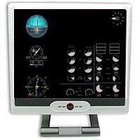
Please remember that you cannot get the PMDG to display the EICAS /
Standby Instruments and Rotary Flaps Gauge realistically, so that is
the reason for using the second networked computer. It runs a program
called FsXpand / FsClient which allows me to configure my EICAS Screen
with the required Instrumentation. You can run this setup
on one computer, but positioning all the Instruments, Switches and
Control Panels on one monitor makes it very cluttered and unrealistic.
------------------------------------------
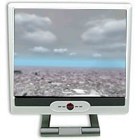
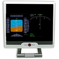
STANDARD CONFIGURATION Understanding
Your Screen
My Screens are set
for 1280 x 960 resolution (the same as the PMDG Panel File. see the
size statement in the panel file) and this is the standard I will use for this
discussion. If you are using a higher resolution, you will have
to make adjustments up and vice versa.
Ok given that i have a Screen Area of 1280 x 960, that means that I
can map any given point on my screen by giving it an address
containing 2 numbers. The vertical point and the horizontal
point separated by a comma. The base position is the top left
hand corner of your screen which has an address of 0,0. The lower left
hand corner will have an address of 0,960. The top right hand
corner has an address of 1280,0 and the bottom right hand corner is
1280,960. Getting the idea ? So you will
be able to 'map' any point on your screen by giving it an
address. e.g. 50,120 1000,50 168,200
etc.
Understanding Gauge & Bitmap Size
OK now you understand mapping your screen, you will also need to
understand getting the gauges the right size. If you look in the
PMDG737 panel.cfg file, you will see in the PMDG_MAIN_PANEL
section that all the Instruments & Controls listed contain a
string of 4 sets of numbers. The first 2 are the mapped position
on the screen of where the top left hand corner of the gauge will be
positioned and the last two are the size of the gauge.
Increasing these numbers will make the gauge bigger and decreasing
these numbers will make the gauge smaller. Get the idea?
Understanding FS2004 Windows & Saved
Flights
When you save a flight in FS2004 containing more than
one view, it will save the information and position of the windows in
the flight file. My experience is that as FS2004 is 'twitchy', that is
it doesn't always do things you expect it to, saving and opening
flights 'Windowed' is the best way. You can always switch to Full
Screen when you are ready to start. See also the notes on switching to
full screen at the end of this page.
----------------------------------------->->

EXPANDED CONFIGURATION for FULL
COCKPIT
The left monitor is simply connected with the right monitor
thru a 'Y' cable to the SVGA output on my video card.
|
|
CHECKLIST
For The STANDARD Configuration you will
need a computer with two video outputs either on the same card
or a machine having a second video card fitted and 2 x CRT or
LCD Monitors. On the BASIC Configuration You
need a 2 Computer Network with the Main Machine having either a Dual
Output Video Card or a Second Video Card Fitted and Configured.
The First Machine is going to run FS2004 and PMDG737. The
second computer is solely to serve the centre Upper EICAS /
Standby Instruments and Flaps Gauge. You will of course need 3 x
CRT or LCD monitors. On the EXPANDED version
you simply need another Monitor to deliver PFD & ND to both
sides of the cockpit.
Notes About The PMDG737
Panel.cfg.File Well what the panel.cfg file does
is build the panel on screen with all the right gauges in the
right places on the Bitmap of the Panel itself. What I did
was first to get rid of the Bitmap image and reposition the
gauges, switches and instruments exactly where I wanted them
displayed to suit my MIP.
The PMDG panel.cfg file, although pretty complicated is just
like any other panel.cfg file, re-writeable. Make a
copy of your original panel.cfg onto your desktop. Open it
with notepad and explore it. Do not change anything nor
save it if prompted. Remember your FS and PMDG are working right
now, so you can always restore the original file if things don't
quite go to plan.
Exploring the Panel File..... You will see various Sections in
the Panel file. We are looking for the section which
says
[Window01] // PMDG_MAIN_PANEL
This is the section which presents the Main
Instrument panel on screen when you load the
PMDG737. It is also the section we will alter to
reposition the instruments. You will also have to move the
file named
737NG_Main_Background_1280.bmp out
of the Panel Folder so it does not display, but not at this
stage.
Understanding the FS2004 Windows /
Views. FS2004 allows us to run several
views which can be 'Undocked' and moved to a second monitor. We
will be utilising this function to help achieve what we
want. Load your flight sim and choose the MSFS B737 making
sure you are not in full screen mode.. You will see on
your screen the outside view over the instrument panel.
There will also be a light panel at the top of the
screen. The two panels are actually windows
overlayed on the outside view. Take the cursor over the
top panel, right click and select 'Close Window'. See it's
gone. FS2004 will only allow
you to Undock Windows in 'Windowed' Mode, so make sure you are
there. Right click the window containing the
Instrument Panel and select Undock Window. Move this window onto
your second monitor. Resize both of your cockpit
windows until they fill the respective screens. Now hit
Alt + Enter and you should have a full screen view out of the
Cockpit & one of the Instrument Panel on the lower monitor. You Do !
Great, You don't ? Go back and check everything.
<-<-----------------------------------------


BASIC CONFIGURATION for SINGLE
COCKPIT
The EICAS Display is being served from the 2nd Networked
Machine running FsXpand /FsClient. -----------------------------------------
OK, LET's SETUP THE PMDG
Load FS2004 in windowed mode and select the PMDG737 with the main
panel showing. Undock the main panel and move it to the second
monitor. Make sure you are in 'Windowed' Mode and save the flight.
Mine is called default. Also make sure that the flight is
saved as the Default Flight. So you now have a startup flight
which loads the PMDG in two views. One has the front outside
view and one has the Main Instrument Panel. It's time to get
serious. We have to get the Instrument Panel Set Up how we
want it. Shutdown FS2004. From the Panel folder, move the 737NG_Main_Background_1280.bmp to a safe place for keeping. This prevents it from being
displayed even though the panel.cfg file will ask for it. Restart
FS2004 and look at what you have displayed on your instrument panel.
Hopefully just the gauges and control/switch panels. Remember
'Mapping' the screen? Remember re-sizing instruments? This is where
you put it into practise. You have to modify the panel file to
suit your own personal needs. No 2 setups will be the same, some
people will want to set out their instruments all on one screen, some
people will want to use a second networked computer for the EICAS,
some people will want to add a third monitor for the full 5 display
type cockpit. So what do you do. First, save your
original panel.cfg file to a safe place for keeping. Next you
can either make a copy of it and edit with notepad or to get you
started, click here for a copy of my
modified panel file. This file does not include the
standby or EICAS instruments as I get my centre display served from a
networked computer running
FsXpand / FsClient. But at least it will give you a start
to help you understand what is going on.
|
|