|
  Nov.
28th 2012
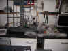
(Day 1) UPS Pulls Up outside & delivers a Package from
SIMWORLD in Poland. It's Colin Batson's 737 Forward
& Rear Overhead panel for building. So you have to
unpack it, check it out and make a start don't you.
My estimate to assemble, wire up and get this forward overhead panel
working in Prosim is about 80 hours. Dont rush this, mistakes creep
in and it takes time to troubleshoot and correct
errors. Nov.
28th 2012
(Day 1) UPS Pulls Up outside & delivers a Package from
SIMWORLD in Poland. It's Colin Batson's 737 Forward
& Rear Overhead panel for building. So you have to
unpack it, check it out and make a start don't you.
My estimate to assemble, wire up and get this forward overhead panel
working in Prosim is about 80 hours. Dont rush this, mistakes creep
in and it takes time to troubleshoot and correct
errors.
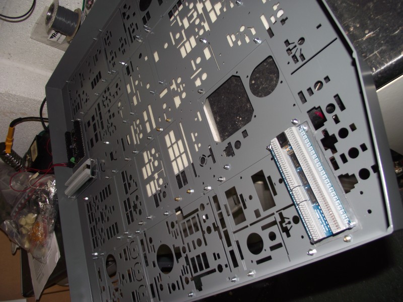
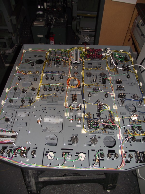
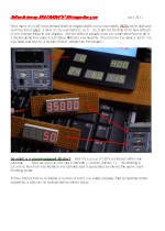
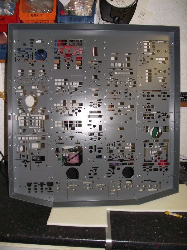
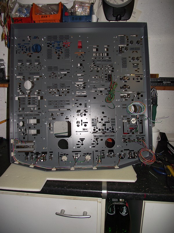
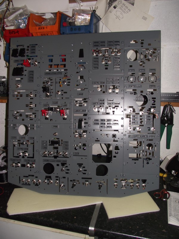
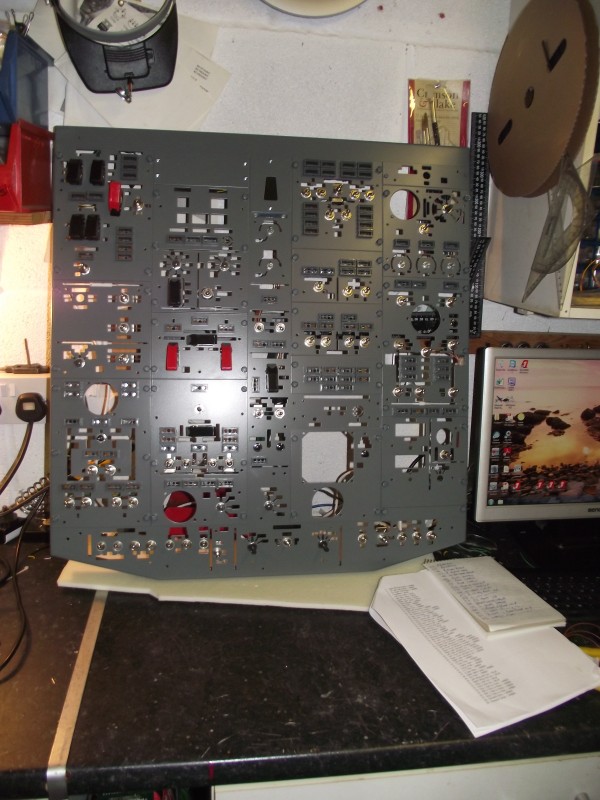
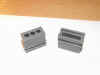
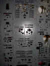
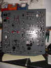
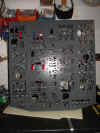
The first component needed is the
frame to which all the aluminium back plates are fixed to using
the DZUS type fasteners. By the way, the packaging
was a work of art.
 Nov.
29th 2012
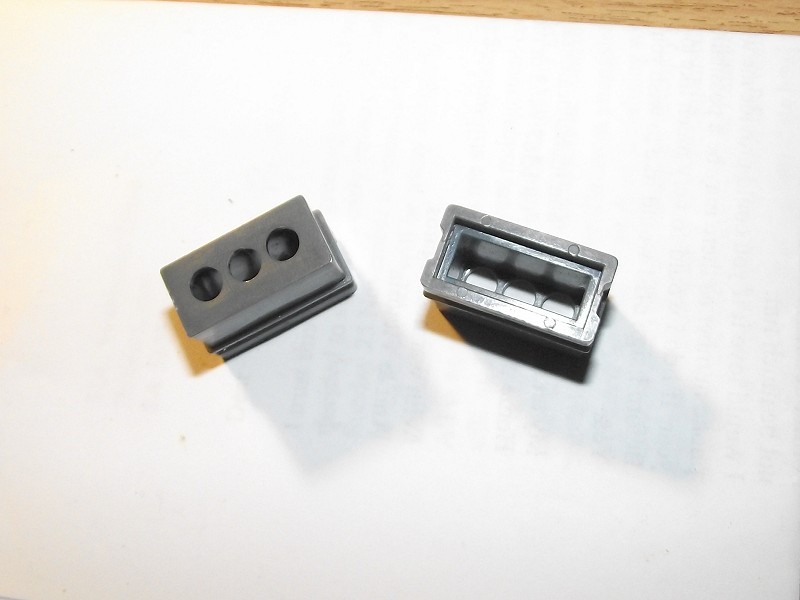
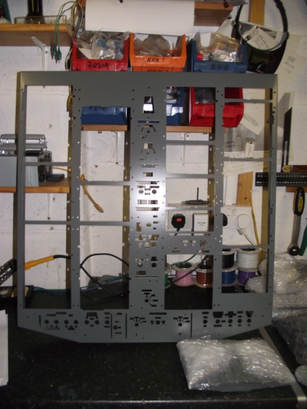
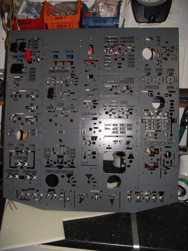
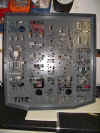
(Day 2) All the back plates fitted to the frame, so then
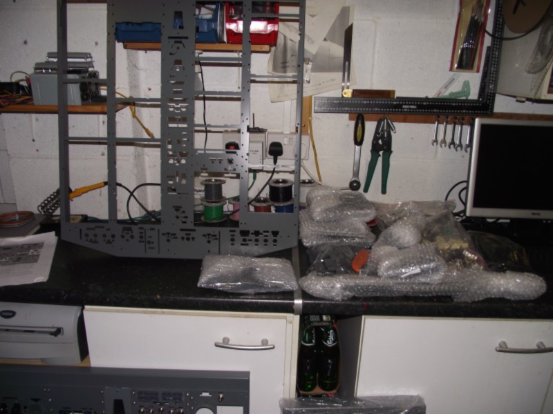
it's time to fit the annunciators. SIMWORLD
have changed the design of their annunciator. Much
better, it's now a one piece 'Push In' Unit that's a tight fit
in the cutouts. However I have also used a spot of
Superglue on each one just in case. With
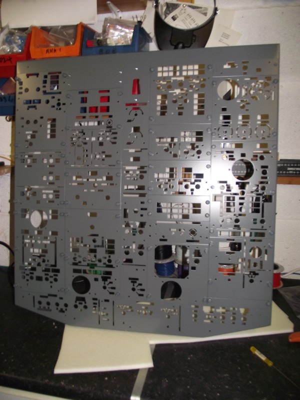
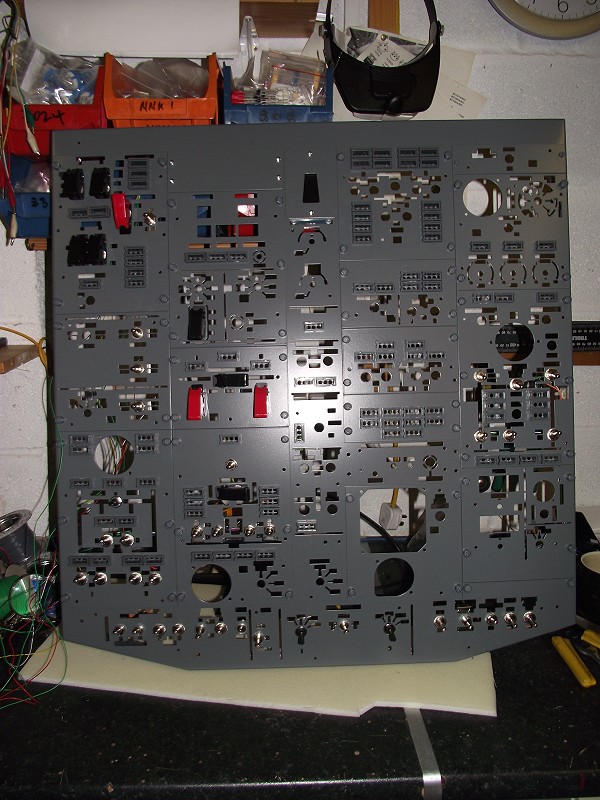
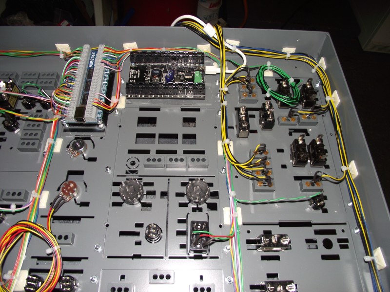
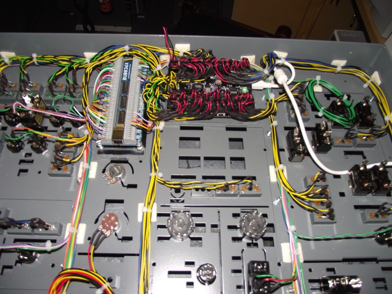
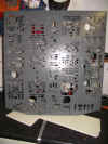
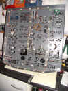
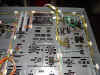
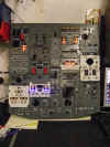
that done, the next job is to decide where the control cards
will be situated. For this particular project,
I am using 1 x BU0836X card, a BBI-32 Input card and 1 x
Phidgets LED64ADV output card to control the
LED's. Trying to hide the cards is not
easy. You have to be aware of not blocking out the
backlight, so this is where i have situated them.
The BBI-32 will go above the Right side of the Light Switch
Panel, the BU0836X will go at the top of the centre column and
the LED64ADV will be situated above the meter panel.
So, that's where I put them. So the next step
is wiring and fitting the switches.
Nov.
29th 2012
(Day 2) All the back plates fitted to the frame, so then
it's time to fit the annunciators. SIMWORLD
have changed the design of their annunciator. Much
better, it's now a one piece 'Push In' Unit that's a tight fit
in the cutouts. However I have also used a spot of
Superglue on each one just in case. With
that done, the next job is to decide where the control cards
will be situated. For this particular project,
I am using 1 x BU0836X card, a BBI-32 Input card and 1 x
Phidgets LED64ADV output card to control the
LED's. Trying to hide the cards is not
easy. You have to be aware of not blocking out the
backlight, so this is where i have situated them.
The BBI-32 will go above the Right side of the Light Switch
Panel, the BU0836X will go at the top of the centre column and
the LED64ADV will be situated above the meter panel.
So, that's where I put them. So the next step
is wiring and fitting the switches.
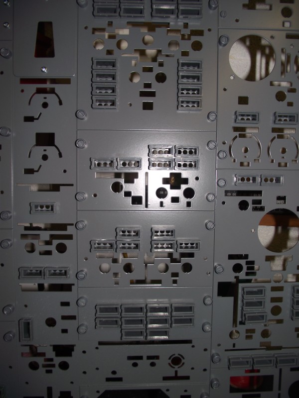
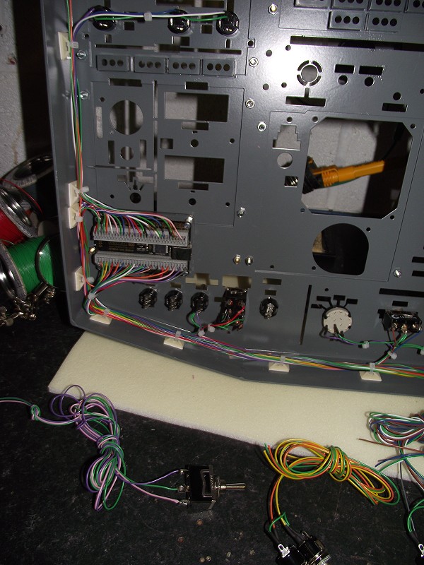
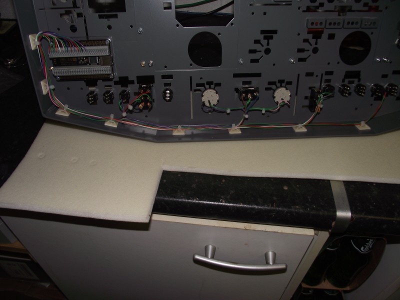
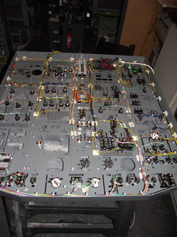
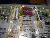
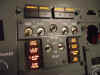
  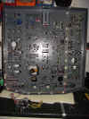  Nov. 30th 2012
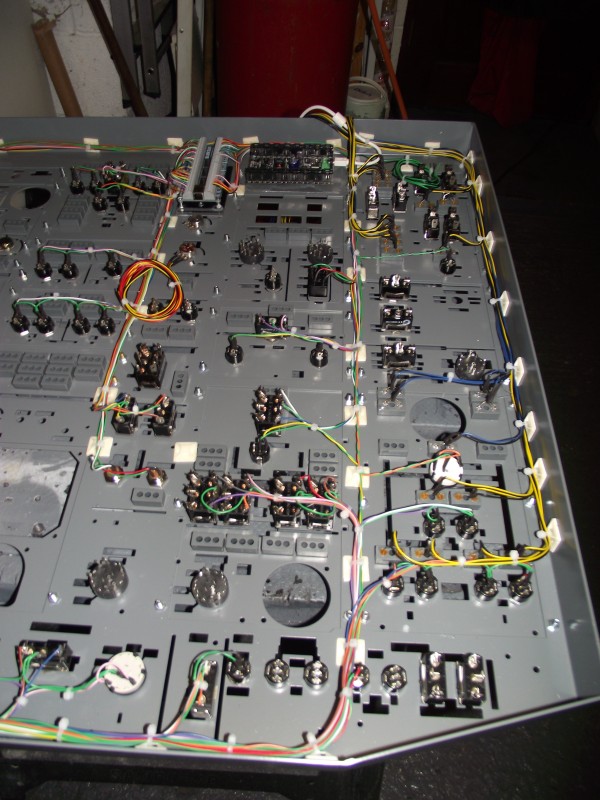
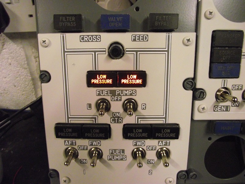
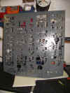
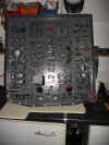
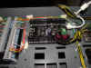
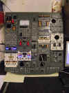
(Day 3) Continue to wire and fit switches. What I do is
start at the bottom and work up each column from one side to the
other. Just bear in mind that the Leo Bodnar cards use a
'common ground' matrix. So that means you can group
switches together on a single ground. For example
the 6 fuel pumps share a ground connection = 7 wires instead of
12. I try to run the cables up between the 5
columns on the overhead and around the outer edges to avoid
blocking any of the backlight cutouts wherever possible.
And of course just keep a mental note of what switches to run to
what card. Nothing worse than having 33 switches to
connect when you get to the card and only 32 inputs - bugger !
Nov. 30th 2012
(Day 3) Continue to wire and fit switches. What I do is
start at the bottom and work up each column from one side to the
other. Just bear in mind that the Leo Bodnar cards use a
'common ground' matrix. So that means you can group
switches together on a single ground. For example
the 6 fuel pumps share a ground connection = 7 wires instead of
12. I try to run the cables up between the 5
columns on the overhead and around the outer edges to avoid
blocking any of the backlight cutouts wherever possible.
And of course just keep a mental note of what switches to run to
what card. Nothing worse than having 33 switches to
connect when you get to the card and only 32 inputs - bugger !
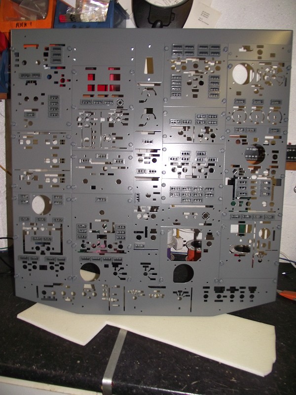
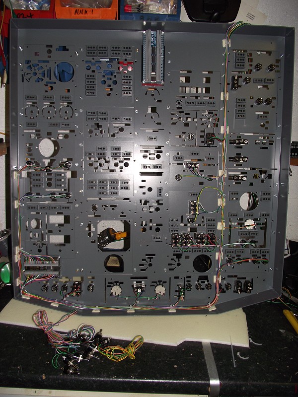
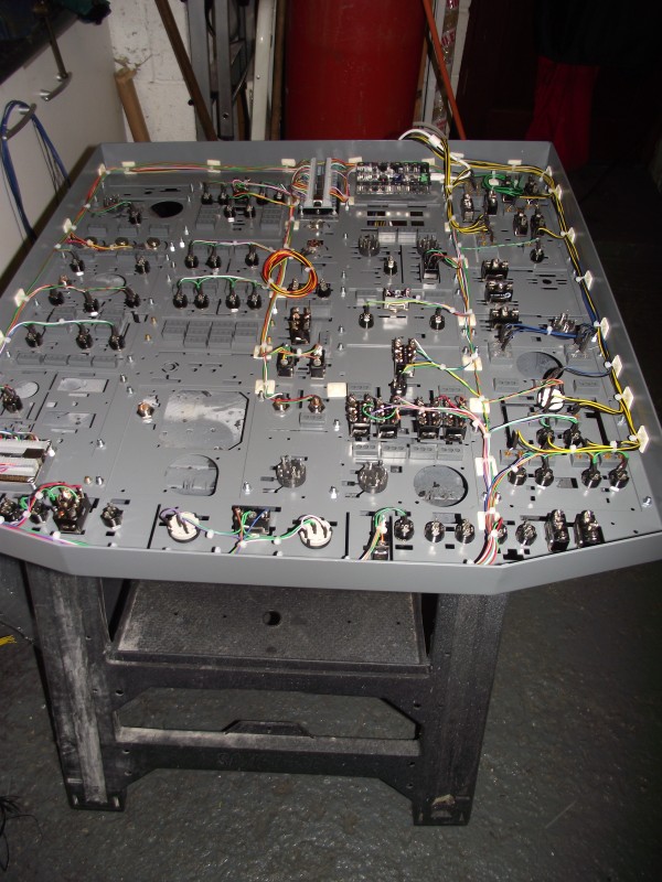
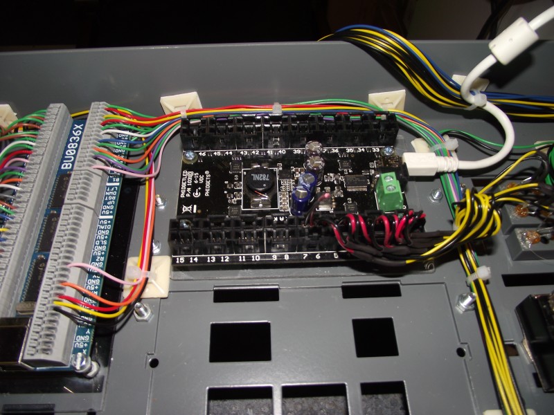
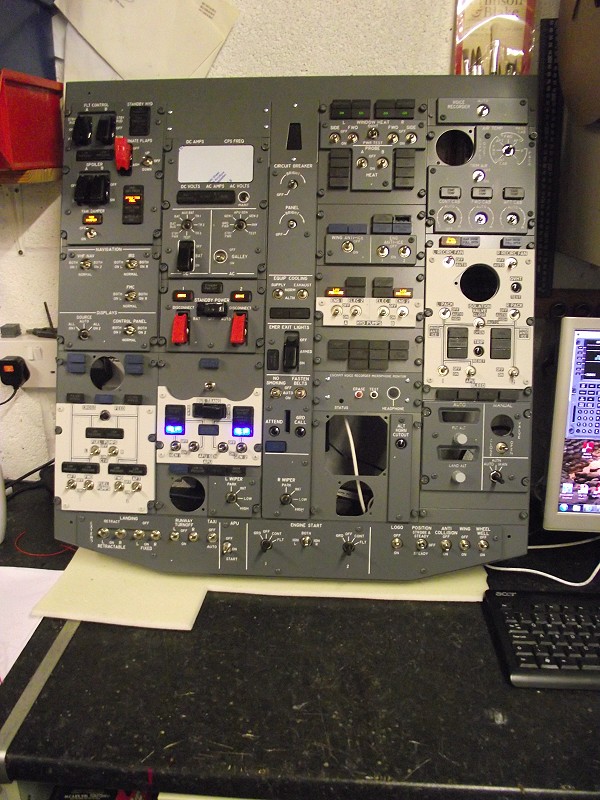
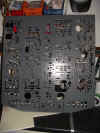
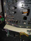
   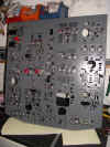 Dec. 1st 2012
(Day 4) Well things have progressed well. The
Cards are fitted, the switches are wired in and connected, so
now it's time to start making the LED arrays and connecting them
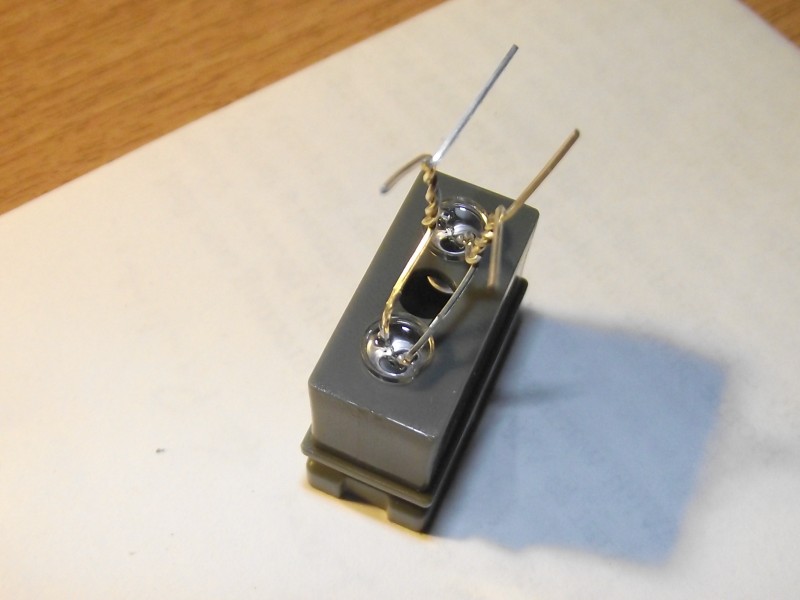
upto the Phidgets LED64. This is a
laborious process. The Phidgets LED64ADV can drive
two Led's per output in Prosim. Join them in parallel.
Just look in the left column how i made the job of joining the
Led's simple. Most Led's have a forward voltage of 2.2 -
2.7v, so i'm going to leave the default settings in the Phidgets
Control Panel set at 2.75v and 20mA per output.
Dec. 1st 2012
(Day 4) Well things have progressed well. The
Cards are fitted, the switches are wired in and connected, so
now it's time to start making the LED arrays and connecting them
upto the Phidgets LED64. This is a
laborious process. The Phidgets LED64ADV can drive
two Led's per output in Prosim. Join them in parallel.
Just look in the left column how i made the job of joining the
Led's simple. Most Led's have a forward voltage of 2.2 -
2.7v, so i'm going to leave the default settings in the Phidgets
Control Panel set at 2.75v and 20mA per output.
   Dec.
2nd 2012
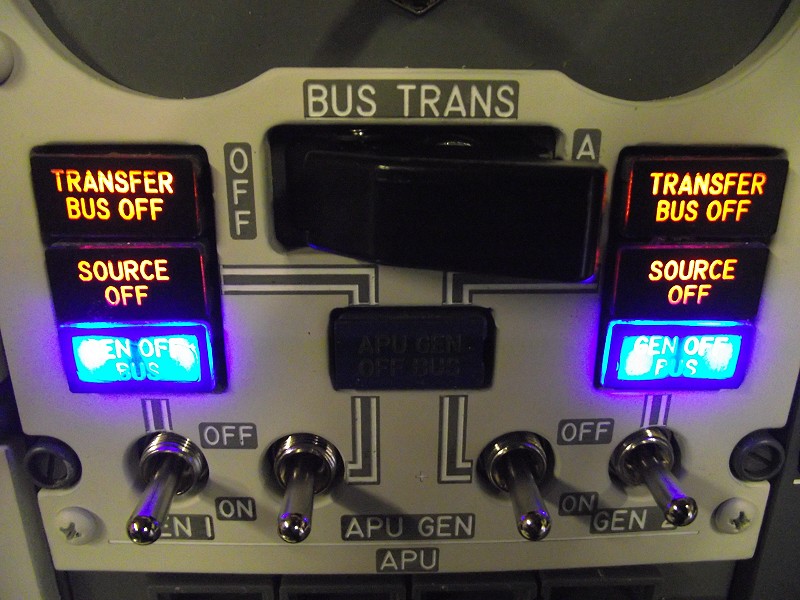
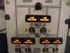
(Day 5) So with the Phidgets card in place, it's time to connect
up to it. just a tip here, what i did was colour code the
wiring. All amber annunciators have yellow an black wires,
all the blue one's have blue/black wiring and the four green
window heat annunciators have green/black wiring.
Then i tried to 'group' them so that for example all the fuel
pumps would join the card together and the two amber and one
blue for each Generator/Transfer Bus Off would be together etc. Dec.
2nd 2012
(Day 5) So with the Phidgets card in place, it's time to connect
up to it. just a tip here, what i did was colour code the
wiring. All amber annunciators have yellow an black wires,
all the blue one's have blue/black wiring and the four green
window heat annunciators have green/black wiring.
Then i tried to 'group' them so that for example all the fuel
pumps would join the card together and the two amber and one
blue for each Generator/Transfer Bus Off would be together etc.
Another point is that the Molex cables which Phidgets supply
with the LED64ADV for joining up are very hard. So,
i tend instead of cutting them in half, trim them off at about
60-65mm before soldering on the led wires. I
actually use two wires per Led. OK, i know the
LED64ADV has a 'common anode' matrix (i connected up that way
once), but as I solder up the Led's to the wires, i want to test
them so i know they are working. I got bitten once.
Nothing worse than an Led not working when you hook upto the
control board. That's soul destroying.
  Dec.
3rd 2012
(Day 6) I've spent all day today soldering connections to the
LED64 card. It's so boring and time consuming joining the
wires, soldering the joint and then using the heat gun on the
heatshrink 128 times, it 'does my head in'. I'm made
for better things than this. Dec.
3rd 2012
(Day 6) I've spent all day today soldering connections to the
LED64 card. It's so boring and time consuming joining the
wires, soldering the joint and then using the heat gun on the
heatshrink 128 times, it 'does my head in'. I'm made
for better things than this.
  Dec.
4th 2012
(Day 7) It's taken me two days to make the Led arrays and
connect them upto the Phidgets card, but at least that's done
and I don't feel suicidal any more so i guess it's time to put
some power on it. It's just so satisfying when a
plan comes together. What needs to be done now
is test each of the 64 outputs in the Phidgets Library and note
what each one is so that you have the list when it comes to
assigning the outputs in Prosim (or whatever your interface
is). If I build your overhead, i will let you have
this list and the Bodnar Card Input List when you collect or I
send the completed Panel to make configuration easy peasy. Dec.
4th 2012
(Day 7) It's taken me two days to make the Led arrays and
connect them upto the Phidgets card, but at least that's done
and I don't feel suicidal any more so i guess it's time to put
some power on it. It's just so satisfying when a
plan comes together. What needs to be done now
is test each of the 64 outputs in the Phidgets Library and note
what each one is so that you have the list when it comes to
assigning the outputs in Prosim (or whatever your interface
is). If I build your overhead, i will let you have
this list and the Bodnar Card Input List when you collect or I
send the completed Panel to make configuration easy peasy.
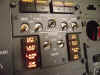
 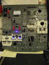   Dec.
5th (Day
8) Right after testing all the Led's (and they all
worked), I applied a small spot of adhesive to each Led to keep
it firm in the annunciator. The holes in the annunciator
as slightly larger than the diameter of the Led, so to avoid any
possibility of the Led coming out of the annunciator, I thought
that was good practise. Dec.
5th (Day
8) Right after testing all the Led's (and they all
worked), I applied a small spot of adhesive to each Led to keep
it firm in the annunciator. The holes in the annunciator
as slightly larger than the diameter of the Led, so to avoid any
possibility of the Led coming out of the annunciator, I thought
that was good practise.
And while I had the glue in my hand, I attached the Legends to
all the annunciators. You have to be very careful
doing this :o)
Dec.
6th (Day
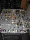
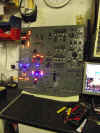
9) Well today, I've spent 'tidying up' some loose ends,
configuring the Inputs and outputs in Prosim and 'Bench Testing
the panel through all the available stages and annunciator
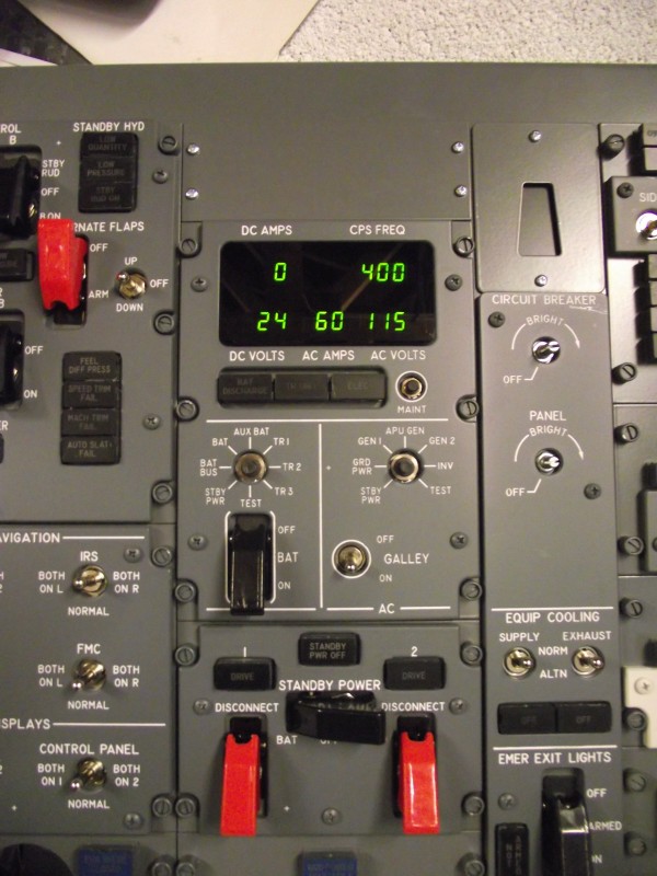
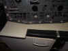
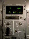
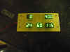
display variations. With that done, I turned my attention
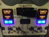
to the Electric Meter Panel and the FLT & Land Alt Dummy
Displays. 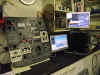

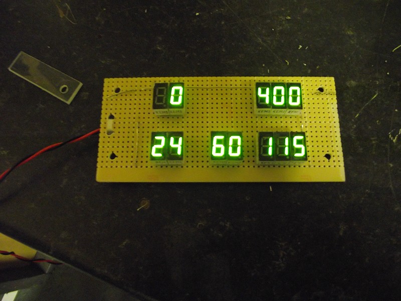
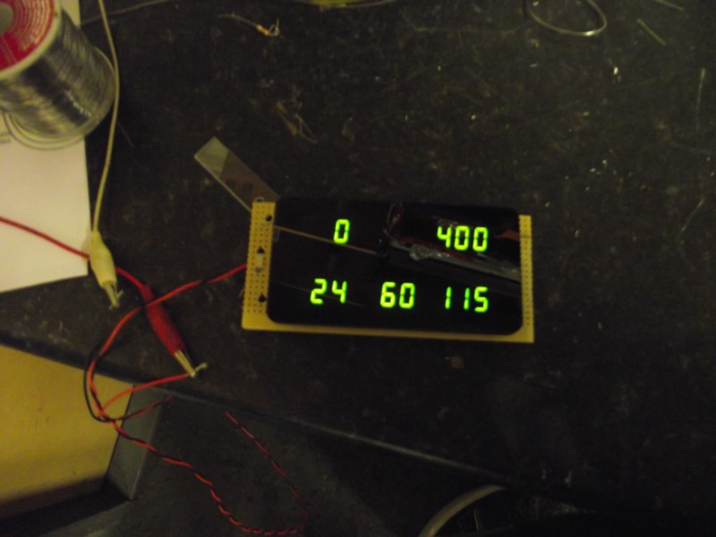
     Dec.
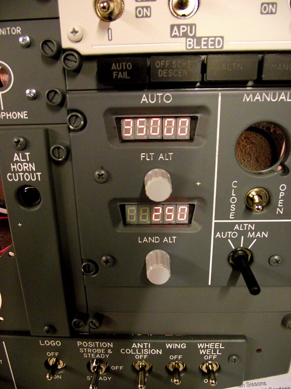
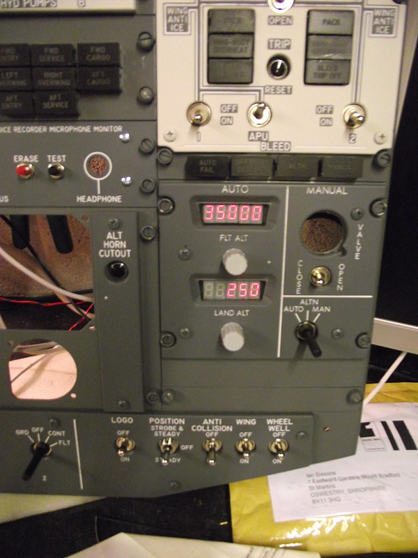
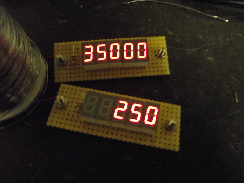
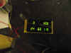
7th (Day
10) Displays, Displays, you want Displays. No
problem at all. These are not difficult to make, just
needs a lot of concentration and time. But the end
result really adds to the 'Cosmetics' of the
overhead panel. If you want to know how to do it, see the
document in the left column. Dec.
7th (Day
10) Displays, Displays, you want Displays. No
problem at all. These are not difficult to make, just
needs a lot of concentration and time. But the end
result really adds to the 'Cosmetics' of the
overhead panel. If you want to know how to do it, see the
document in the left column.
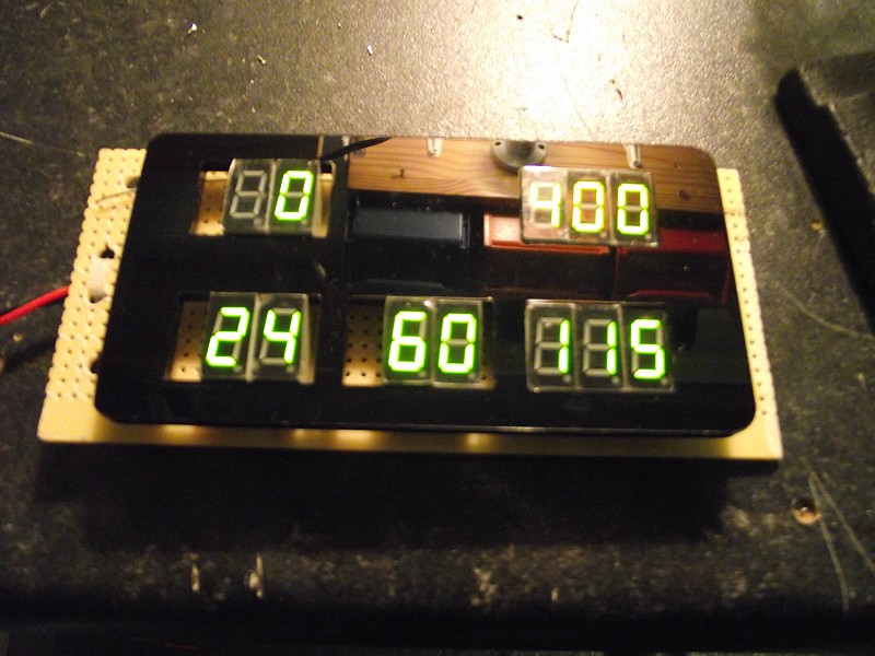
The only issue I have is that the 5 7 segment displays for the
Land and Flt Altitudes do not fit the window. So there
will be an issue with 'light leakage' when the backlighting is
applied. To overcome this, i've surrounded the digits with
Black Modeler's Clay before fitting them and then trimmed it off
once the adhesives were dry.
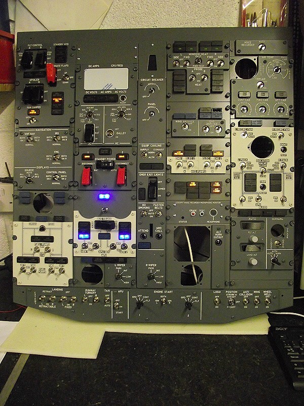
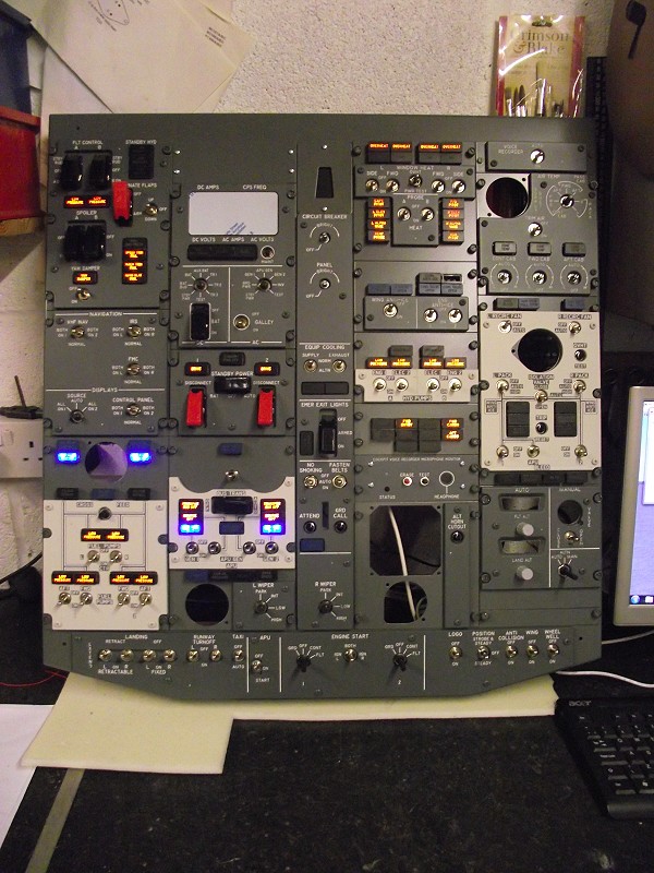
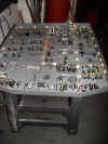
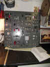
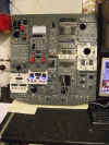
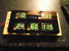
Dec.
8th (Day
11) The operation of the Overhead is now 100%. It's
working in Prosim exactly how I intended, so all I have to do
now is finish the cosmetics like fitting the gauges and the
stickers. I'll upload the Photo's when I have them
ready. Tips
& Tricks
1. All 'Common Ground' Inputs To The Bodnar Cards are Green so
are easily identifiable when you come to connect.
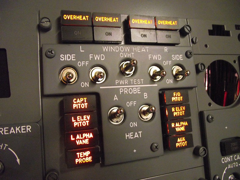
2. Keep all The annunciator Anode wires 'colour coded'. That's
yellow for amber, blue for blue and green for green.
3. Keep annunciators in their group together. e.g. 6 x Fuel
Pumps, 4 x Anti Ice etc. Allows consecutive connection to
LED64ADV.
4. To Prevent Light Leakage from the back lighting, use Black
Modeling Clay to fill the gaps.
|